Battery Charger Schematic
Interview with Lee Hart

I'm talking to Lee Hart, a well-respected electrical systems adviser in the EV community, about his "bad boy" battery charger schematic, who recommends teaching your bad boy a few manners before you turn him loose on your expensive batteries.
Lynne: I'm looking at this battery charger schematic you contributed to the EV discussion list.
Lee: That's the "Bonn charger" schematic, invented by Don Bonn.
What's a bad boy charger, anyway?

The classic "bad boy" charger is a bridge rectifier and enough extension cords to serve as resistor to limit the current so it won't melt cords or trip circuit breakers. From the 120vac line, they are generally useful for 96v to 132v packs. At 96v or less, the current is so high that it destroys things. At 132v or above, it won't quite fully charge the batteries.
Extension cords? You mean you just add a bunch of 100 ft. extension cords for resistors?
That's what they do. Understand, this is not my idea; it's just what some people have done. Ever seen the "Red Green" Show? It's their style.
How many extension cords do you think would do the trick?
Don't do this, okay...the resistance is completely unpredictable. For example, if you coil up the cord, it can melt. Getting the picture? Too many things can go wrong for this to be practical!
I know I shouldn't, but what can I say? I have this well-known weakness for bad boys.
I'm not saying you can't have a long, happy relationship with a bad boy. I'm just saying that if he's gonna be a useful charger, you're going to have to civilize him a little bit. This means adding:

- A fuse or circuit breaker so you don't fry something;
- A timer to automatically turn it off;
- A voltmeter and an amp gauge so you can see what you're doing;
- Some kind of "controllable impedance" so you can set the maximum charging current.
Elaborate on that last one, please?
Types of "controllable impedance" you can use in your charger
An "impedance" is anything that acts like a resistor. It can be an actual resistor, an inductor, a capacitor, a transformer or autotransformer, a phase-controlled rectifier, or any combination of these.
A resistor can certainly act as a resistor; ) It's the cheapest, and also the least efficient. It converts the voltage difference between the AC line and your car's battery pack voltage into heat...so the result is that it gets hot!
That might be a drawback.
But it would work, if you could deal with that issue.
Next are inductors and capacitors, which limit the current by shifting the phase between the AC voltage and current. They go in series with the AC input to the bridge rectifier. These don't get nearly as hot, but they make the power factor worse.
Meaning?
You can't draw as much charging current from the AC outlet. Let's take these one at a time:
An inductor is a fist-sized coil of wire on a transformer-type E-I core. As I said before, it goes in series with the AC input to the bridge rectifier. Inductances of about 0.1 to 2 millihenries are about right. If you're making one, includes some taps so you can easily adjust the inductance to control the current. You can also adjust the inductance by stacking all the core's E's in one stack, all the I's in another, and adjusting the size of the gap between them with paper or cardboard shims.
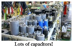
A capacitor is a big AC-rated metal can of about 10-100 microfarads. They are generally AC motor "run" capacitors rated at 360vac or more. Word of caution: Don't use an "electrolytic" or "starting" capacitor!
Why not?
The capacitor will burn up. It might even explode.
There are two kinds of big capacitors: electrolytic "starting capacitors", which are only used for a few seconds at a time to start the motor, and "run" capacitors (usually plastic film, or an oil-filled metal can with paper and foil). You want a "run" capacitor rather than a "starting capacitor".
Capacitors will be bigger and cost more than inductors, but they're easier to find used or surplus. They can't be adjusted, so you generally need a collection of capacitors that you can wire in series/parallel combinations to get the desired current.
Then there's autotransformers.

Autotransformer...is that the same thing as a variac?
Yes, a variac is a type of autotransformer that happens to be adjustable with a knob instead of my switching between taps.
An autotransformer is somewhat like an inductor, but has a better power factor and can step the voltage up or down. With the proper one, any battery pack voltage can be charged from any AC line voltage. These are sometimes called "third world" chargers.
"Third world" chargers?
"Third world" battery chargers are just simple chargers that actually work reasonably well, but are built using old or cheap technology.
I thought they were called that because of the ability to switch back and forth between incoming voltage lines.
That too.
Hey, that sounds pretty useful!
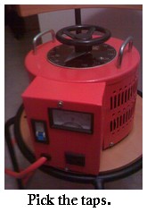
Yeah. On any autotransformer, you can switch back and forth between 110 and 220v lines by picking the taps on the autotransformer.
What's "picking the taps" mean?
Choosing which taps you want to use. A "variac" is an adjustable autotransformer that makes this very easy.
Oh. I get it, now. Finally. Okay, so that's it for autotransformers...
Yes. Remember on these that the efficiency and performance are good, but the downside is that the autotransformer is big and heavy.
How big and heavy are we talking, here?
About 10 pounds per kilowatt.
Hm.
The output is not isolated on an autotransformer, one side of it is connected directly to the AC line. Regular transformers have an isolated output. They weigh more like 20 lbs. per kilowatt.
And transformers...

Which brings us to transformers.
Right. Next step up is to use a transformer instead of an autotransformer in your battery charger. Now you have a conventional transformer-rectifier charger, by far the most common kind commercially. They work as well as the autotransformer, but, as I said, they have the added benefit that the output is isolated. But heavy!
I read this at Wikipedia: "A failure of the insulation or the windings of an autotransformer can result in full input voltage to be applied to the output." Sounds like a battery barbecue waiting to happen! Is this a reasonable concern, or do these things give you plenty of warning before they fail?
It's possible for them to fail, but transformers and autotransformers are normally very reliable (aside from cheap junk or user abuse).
If a winding does open, it will probably give no warning. An open winding normally means less charging current, which is a safe direction. Or, a winding can short, which will generally blow a fuse or circuit breaker (assuming your "bad boy" has these).
If reliability is vital, there is a special kind of transformer called a "constant voltage transformer". They have a semi-regulated output voltage, intrinsic current limiting, and have no failure modes that cause an excess output voltage or current. Lester (for one) uses them in their battery chargers, which are very common in the golf cart industry.
And finally, you can use a phase controller for controllable impedance. This is a simple electronic circuit with SCRs or triacs. A light dimmer is a common (low power) example of a phase controller.
That sounds like a cheap, easy solution.
Yes, they are cheap and efficient, but have a terrible power factor and generate a lot of noise (radio interference).
Use a combination for better results
So is there a "best" solution?
Yes - you can combine them. Combining the above devices often produces better results than any one by itself.
For instance, an effective combination is to use the 120v-to-12v transformer out of an old 12v battery charger, a home dining room light dimmer, and a capacitor. Use the light dimmer to control the primary voltage of the transformer; it will adjust its output from 0 to 12vac. Now wire this isolated 12vac in series with the 120vac line itself. Depending on the polarity, you now have an adjustable 120 + 12 = 132vac source, or a 120 - 12 = 108vac source. Use this to power your bridge rectifier. Wire the capacitor directly across the AC line to correct the power factor somewhat. With some fiddling, this will charge your 132v pack adequately.
Awesome! Thank you, Lee.
That's all there is to it! You can see the Bonn battery charger schematic here.
Lee emphasized that he does not recommend any kind of bad boy charger for beginners, that they are a very good way to get shocked and/or to fry some very expensive equipment.
If you want to talk to Lee about his battery charger schematic, you're welcome to join the EV discussion list.
|
|
|
Recent Articles
-
Electric Car Conversion Using E-Golf Power Train
Mar 06, 20 05:30 PM
 I own a '19 VW E-golf and would love to transplant the electric powertrain into an old beetle or possibly a Thing (if I can find one cheap enough). Would
 -
𝐓𝐰𝐨 S𝐢𝐠𝐧𝐢𝐟𝐢𝐜𝐚𝐧𝐭 𝐕𝐞𝐡𝐢𝐜𝐥𝐞𝐬 L𝐞𝐚𝐯𝐢𝐧𝐠 𝐭𝐡𝐞 𝐑𝐨𝐮𝐭𝐞 𝟔𝟔 𝐄𝐥𝐞𝐜𝐭𝐫𝐢𝐜 𝐕𝐞𝐡𝐢𝐜𝐥𝐞 𝐌𝐮𝐬𝐞𝐮𝐦
Nov 11, 19 09:51 PM
On this upcoming Saturday, November 9th, a transport truck and trailer will roll into Kingman, Arizona from Los Angeles, California to pickup our very rare circa 1959-1960 Henney Kilowatt with only 40… -
Electric Car Facts and FAQ
Nov 07, 19 04:21 PM
 Electric car facts and frequently asked questions from the e-mail bag. There's no such thing as a dumb question!